|
Saga of Gas Gauges car 689, a 1973 posted in June, 2011 Here is a nice Video from the web on this general subject. http://www.youtube.com/watch?v=S7ccqSgfrRo
After fiddling a lot with my 1978 Glassic gas gauge, I find that my new, older 1973 also had a hokey gas gauge reading, so I set about to use what I had learned below and add to it to try to fix my gauge. Here is what I found out. The gauge was reading less than half when full, and less as it emptied. I had found a replacement gauge on Craigs list, and it was for a Ford -- they have the right resistance range for our cars -- I think something like 73-10 compared to completely different numbers for a Chevy gauge. Those are the ohms of resistance of the signal in sending unit inside the gas tank, 10 when full, 73 when empty. What you have is basically a dimmer switch inside the tank, yes, with an electric signal in it, and as the float arm goes up and down, the switch slides and varies the electric going to the gauge -- the gauge then makes the needle move according to the electric. If that is not complicated enough, there is a tiny voltage regulator behind the dash that changes the 12 Volt car power to 5 volts that the instruments use to power themselves. It supposedly pulses the 5 volts to the instruments. If that device goes bad, that also can mess things up.
above - this view is up and under the dashboard and the gauge just below the red arrow is the back of the temperature gauge, the gauge on the driver's side. Below the point end of the arrow is the nut that holds the top of the gauge in place, and also the flap of steel that holds the regulator. Directly between the green and blue wire connectors in the pic. are the two spade connectors hooked onto the voltage regulator (see picture below). The Drivers side connector (on right in picture) is the 12 volt power which goes into a cluster of wires, and the left connector (passenger side) goes to the gauges.
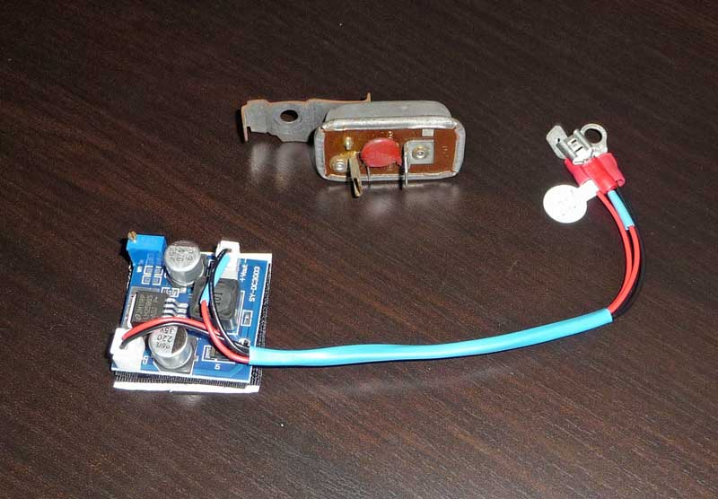
above: front and back views of the regulator. Mine had the markings IGN on the right (probably for "ignition" and a number 2 just below that red component looking thing. -- a resistor or something. No other markings were on it. THE THEORY: So, power comes from the car at 12 volts - into this regulator, then to one side of the gauge. The lower power than goes out of the gauge, back to the sending unit in the gas tank, through the gas sending unit and out the other wire at the sending unit which goes to ground. That completes a "dimmed" circuit that makes the gas gauge needle move a certain amount, depending on how much the float arm arcs up and moves the amount of electricity going through the "dimmer". Here is more from the web (only stated better) http://www.fordification.com/tech/fuel-sending-units.htm WHAT CAN GO BAD: The sending unit can go bad inside the gas tank, including the float leaking and sinking. The wiring and GROUNDS can go bad, the gauge can go bad, and the "instrument panel voltage regulator" can go bad. In the case of my 1973, since I had removed the sending unit before (a messy and, in my mind, dangerous job) only to find out that it was the gauge. This time I decided to stay out of the gas tank, and only fool with the sending unit if all else failed. TESTING THE GAUGE: Websites for Ford say that you check the sending unit by disconnecting the wire that goes to the sending unit and, with the key in the on position (and I surmise, someone else watching the gas gauge) you SHORT OUT the wire going into the sending unit to the frame of the car with a piece of wire. That would make it not go through the "dimmer" part of the sending unit at all and be like full power - that should make the gas gauge shoot up toward FULL which would be 10 ohms of resistance and peg even beyond full or zero resistance. That means the gas GAUGE is working. As soon as it goes up to, and beyond full, I would stop the test - common sense) So I replaced the gauge with this Autometer gauge that had no marking on it saying it was for a Ford (but the seller was a Ford nut and seemed to have a good reason for selling it) The new gauge did not work right either, and not only read low, but now it was hopping about and moving around some. That is when I disconnected and put a volt meter on the wire going into the sending unit at the back of the car -- the voltage was hopping around between 0 and 5 volts, but showing various other readings every second or two. Kind of spastic. remember, the car key has to be in the ON position for this to be powered up. Since the "testing the gauge" thing worked ok with the new gauge and since the meter readings did not look "smooth" I decided to try the voltage regulator. So, I have removed the voltage regulator and will get a replacement. It looks like it will be $20 to $40. In looking on the web, I found zero regulators that
were from Ford products and matched the one above. Some were close, but
had different mounts. An email to Joel (who is Joel?)
suggests that maybe they were still using International Harvester Scout
voltage regulators at that time. A web
above: a new type of voltage regulator ordered from
eBay - this supposedly levels out the fluctuations in the original type The new voltage regulator seemed to work fine, but the
gas gauge still showed nearly empty when there was over 5 gallons in the
tank. I figured that the sending unit was worth more than
$50 and I still could replace the steel tank with the plastic one if I
ever felt like it. When I got home, Now all I have to do is run the tank down to almost
empty, and swap out the sending units. I will take pictures of that,
along with the SENDING UNIT REPLACED Draining the gas from the tank was the biggest part of
this swap. Here I will show what I did, in the hopes of saving you some
legwork. This
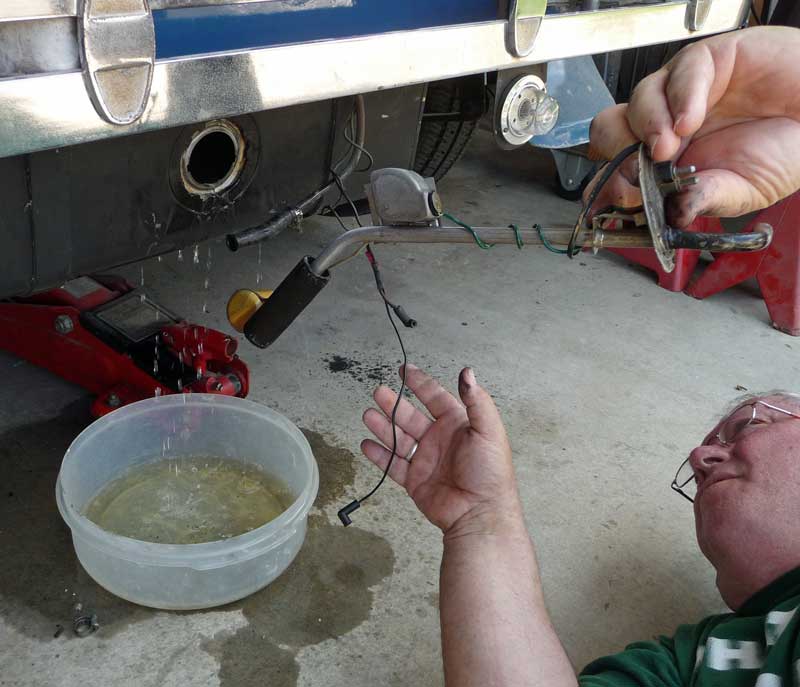
Since the gas tank was nearly full, I got a siphon
hose thing from Harbor Freight (the discount tool places) $5.00 and
drained Then I disconnected the hose and let another gallon or so drain into a pan on the floor. The flow stopped.
Then I twisted the ring that held the unit into the gas tank - and nothing happened - THEN I twisted and pulled on the sending unit pipe and the seal for the gasket broke and a couple more buckets of gas poured out. No smoking, please. After that, the gas was still level with the hole where the sending unit came out, so I stuck in the siphon hose and pulled out another gallon of gas.
Here is the ring that holds the sending unit in place.
It works like garbage disposal hangers, if that helps. The ring has 3
tabs that are
You can see the ring's tab on the left with the white
edge that gets narrower as it was pressed in behind that tab. A couple
of taps counter-clockwise on the grabbers
Gasket! This was a bugaboo in my first switch out. They do not come with a sending unit, for some reason. They can be ordered separately, or, I reused both of mine. Handle them carefully so as not to break them. The newer sending unit for the plastic tank that I had bought was very similar, but the gasket on that one, while nearly new, looked about twice as thick as my original one and likely would not have worked on the metal tank. Putting it back and keeping it from flopping around and sliding out of place is tricky. Here is what I learned. First, test-fit your installation without the gasket, then use vaseline to gob onto the gasket and hold it in place in the groove on the gas tank hole while you place the sending unit back.
Out came the old sending unit. The float WAS in place and did not seem to leak. The black thing near the float is the gas pickup and filter. The device on the center top is the resistor thing. More on that later when I open up that unit, since IT may be able to be cleaned up and gotten working again.
Old (left) and new sending units. You can see, on the old unit how the wire arm for the float is soldered onto the post in the center of the unit. That is what pivots that post and changes the resistance
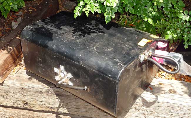
Here is the plastic tank I bought. In comparing the measurements, they were almost identical. The difference may be the thickness of the plastic one. metal: 10 1/4 inches high, plastic 11 inches high There are 3 hose connectors on the right (not counting the gas filler tube). This item has a warning sticker on it that says "keep exhaust pipes 3 1/2 inches away from tank. My old exhaust is about 1 1/2 inches from my metal tank.
The plastic tank looks like the sender is held on with home-made scraps of aluminum. I think that the tanks come that way, I think. That is probably why they needed a thicker gasket.
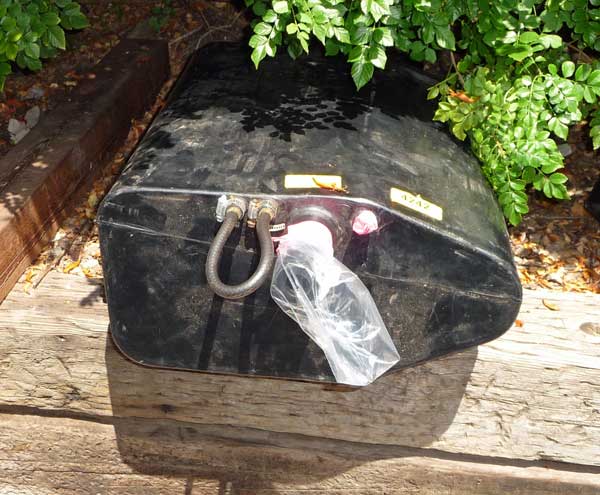
Here is the end view of the plastic tank. Look at how thick the filler neck plastic is.
Grooves in the tank hole sides and tabs on the sender make sure that you have it aligned right side up and straight. You have to look as you slip the sender in since the alignment is a bit awkward.
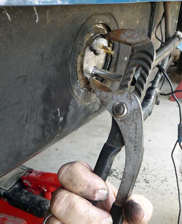
Once you get the unit in place and the locking ring hooked in all three grooves, and no hunks of gasket falling out (my gasket seems to have stretched a little over the years) then you can start to tighten down the tabs. I may have said this the last time I did this (below) but the word Spanner wrench comes to mind. I got my channel locks and opened them the right amount to put the bottom jaw on the right of the bottom tab, and the top jaw on the left side of the top tab and twist to tighten. The ring wanted to go off-center but when I got it right, it smoothly went into place. When time permits, I will show some resistance meter readings on the old sending unit, try to clean it, and see if the readings make more sense. Somewhere on the web it said that these units can be "rebuilt".
Above - I opened up the sending unit hub by
straightening the three tabs (circles on the left side) and you can see
the resistor inside. I am not reporting the readings since, in my mind, they did not clearly show a major change, although the readings DID show that the unit measurements were closer to the original 73-10. Since the filter for gas (black thing center top of the above pic.) was dried out and cracked open, I threw this unit away.
The GUTS of the sending unit showing the 3 tabs back in place, the shaft welded to the float arm, and the filter, no longer with its black covering on it. Testing the resistance between the posts of the sending unit is done with a multi-meter (you can get a cheap one at Harbor Freight tools) and you use the resistance setting (the ohm symbol, which looks like a little set of headphones) -- I set the range to 200 not the larger numbers like 20,000. ****************************************** Different fuel sending unit installation in a 1966 2/2008 -- Received from Dennis, car 189
I used the old gasket, still in good shape under the new ring I
cut then with self tapping screws, screwed the new unit to the new ring.
Worked like a champ. All this work could have been avoided if they just
made a sending unit with a 3 1/2 inch diameter top and matched the 1966
gauge I had. (Wishful thinking) I brought the old sending unit to at
least 6 places including boat places and no one, even the old timers,
even had a clue. One guy thought it may have come from a boat. Well
that's my story and how I installed a new sending unit. Pictures coming
soon...
Received 10/2005 from Ron, car #221, a 1967:
************************* THIS PAGE HAS TWO TOPICS. First, I replaced the fuel sending unit, and then ended up replacing the gauge since the sending unit turned out not to be the problem. The gauge was bad. The info below pertains to car 1254, a 1978, but may be useful for other years too. On a trip last fall, my 1978 Phaeton's gas gauge went ape. After filling the tank, the gauge pegged way over past full. In watching the miles per gallon, when the tank was ready for a refill, it had only moved down a bit - it still showed slightly above FULL. I record my repairs for other NON-mechanics, like myself. The consensus was that the fuel tank sending unit likely went bad. Inside the gas tank, sits an arm and float device - similar to the ball and float in a toilet. The float arm is connected to a variable resistor -- as the gas level goes down, the resistance changes, changing the amount of electricity going to the instrument in the dash, thereby causing the needle on the gauge to not travel as far. Anyhow, the resistors go bad and the sending unit needs to be replaced. The car books say that replacing the sender is a "starting point" -- in my case it did NOT solve the problem. When my mechanic was too busy, I decided to try to change this myself. |
|
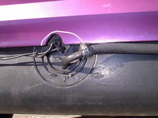
Here is the sending unit. It sticks into the middle of the back of the gas tank. In order to remove it, you have to loosen the bold holding the strap that holds the gas tank, on the passenger side. In that way you can lower the tank some to get the unit out. Note: later on, while fooling with this, I took a moto-tool and enlarged the notch in the back apron so that it was smooth and followed the arc of the sending unit. I touched up the edge with paint and it looked better and allowed me to remove the sender without loosening the tank. I used a compass to mark the car so it looks better than that white line in the picture above. |
|
| Tip #1 -- get MOST of the gas out of the tank first. I drove the car
to a bit less than half a tank, and that was NOT enough. Do this outside
so the gas won't stink up the garage. Tip #2 -- Don't smoke while doing this. You unplug the two wires -- by pulling out on them in my case, and disconnect the gas line - tucking the gas line UP behind the bumper (a good bit of gas will dribble out of the hose if you let it lean downhill) Then remove the unit by turning the ring that holds it counter clockwise about a quarter turn. There are three places where the ring wedges into grooves in the mounting place of the gas tank, and you turn the ring enough to free where it is wedged in. Tip #3 -- I feel that there is a tool for this turning job -- could it be called a "spanner wrench" - I don't know, but I use a screwdriver and banged on one of the four prongs that stuck out of the ring to nudge it counter clockwise. What I SHOULD have done is wedged a square shanked screwdriver between two of the adjacent prongs and used that as a fulcrum to twist off the ring. You need to be careful doing that to be sure you aren't leaning your tool against the gas inlet or the electrical connector when you put pressure on it. |
|
 There is the unit out of the car. The most VALUABLE thing on the page is that ring on the bottom. Apparently, new sending units do NOT come with the ring, so don't lose it. Closest to you you see the three prongs on the ring that tuck into the slots on the gas tank. You put the ring in place in the three skinny places and then rotate it -- at the top of the ring, on the underside you can barely see one of the 4 prongs that stick out in the back -- those are to tighten it down. The float is on the right, and the black thing is a filter. Tip # 4 -- take your time maneuvering the sender in and out of the tank. I banged mine on the edge when removing it and the filter fell off in the tank. Fishing it out was quite a trick. |
|
| Getting a replacement part. I thought that would be the easy part. It wasn't. Nobody locally had ANY - Tip # 5 This car uses a 1970 or so Ford BRONCO sending unit, not a Mustang one. A Mustang sender fits in the opening, but the inside is different and designed for a deeper, smaller tank. I do not recommend the substitution. |
|
The above description came from a website wildhorses4x4.com/16.asp They had the correct item for $65 plus postage -- They also had those retaining rings for $9. There are other on-line sources too. I don't know these people -- they were the first ones I found using Google. An order to them in March 2005 did not go well. They had been on backorder for quite some time (yet their website made no mention of that), they have no provision for quoting postage cost until after you order something, and they did not respond to my order until I sent a follow-up email. I would only suggest using them for reference info or perhaps ordering by phone. Tip # 6 I ended up using Vaseline jelly to hold the gasket in place, and to slick up the parts to they would slip together without bunching up the gasket. BACK TO THE MUSTANG unit: The gas line to the engine is a metal line that seems, in my case to end about the middle of the gas tank above it. At first, I was going to just swing the hose around so that it approached from the driver's side, but it put too many bends in the hose, which probably should have been replaced anyhow. I suppose I could have cut the metal tubing, flared it, and put on a new hose to approach from the drivers side. I ended up having my welder cut off the line ending on the Mustang sending unit and put it on facing the way the old one was facing. $12 for the welding job. Tip # 7 -- Although I was able to bend the tube INSIDE the gas tank to match, when I tried to bend the outside part, the vice made a small leak, which I ended up patching with a piece of gasket and a hose clamp. I only mention my use of the WRONG PART since Mustang parts are generally easier to find than Bronco parts, and I saved about half the money of a Bronco part - if you don't count my making myself crazy trying to make it fit right. Best idea? Get a Bronco sending unit. As it turned out, the gas gauge was bad, not the sender. I ended up "rebuilding" the sending unit. I spotted a web page on a Bronco website and took the old sender apart, cleaned the contacts and put it back into the car. It seems to work fine now. |
|
|
GAS GAUGE REPLACEMENT Having replaced the sender and seeing the same results (with an empty tank, the gauge still read slightly above half a tank) I decided to try a new gauge. I got an Auto Meter 2 inch (actually 2 and a sixteenth gauge to fit a 2" hole). I got mine at Automotive Engineering Performance Centers only because they were close by. It cost $34.99 in May, 2005. It looks similar to the original except that it has a dull aluminum color bezel (ring around it). You must specify that the gauge is for a FORD - my box says: "73 ohms empty, 8-12 ohms full For most Fords before 1989 and most Chrysler vehicles." Well ! The wires and terminals did not match the old, outgoing gauge, so it took some trial and error to get it to work. Below is what I learned, but use this info ONLY as a guideline in your efforts. I did a lot of trial and error and THINK that below is the final working solution. TIP: number the wires with a piece of tape when removing from the old gauge. Below are the numbers that I used. OLD GAUGE REMOVED
NEW GAUGE INSTRUCTION SHEET
Wire # 1 is the source of electric for the gauge. Wire 2 sends power out to the sending unit # 3 wire has two wires joined together. That is because it is the wire returning from the sending unit, and the second wire is to the ground. In a steel car, I guess the gas tank itself is grounded to the chassis. Wire # 0 is taped over. It has two wires and is not used on the new gauge, so it is just covered up as a pass-through. In my various mis-wirings, I caused a direct short, since the #3 wire on the original gauge is NOT a ground, even though the gauge says "G". I also pegged the new gauge over on the FULL end (way past full) - because the two positive wires ( #0 and #1) do two different things - one deals with the dash lights and the other with the power for the gauges. As a result of my trials, I lost my dimming capability for the dash lights, and may have burned out that part of the head light switch. I MAY have been able to repair the old gauge. Between terminals 1 and two is a little electronic component - a resistor or whatever. I didn't remove that to see if Radio Shack etc. could figure out what its purpose was, but I would not be surprised if it had gone bad. CAUTION: When reinstalling wires keep in mind that the instructions are backwards since you are looking at the back of the gauge. Wire # 1 ends up on the driver's side when the gauge is in the car, etc. |