GlassicAnnex

Technical -- Chassis


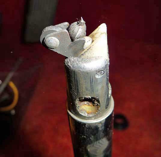
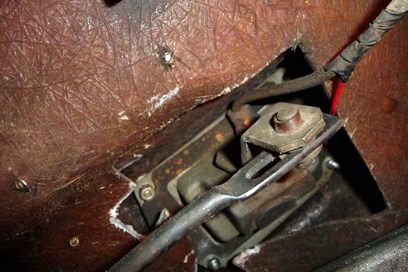
12-33    Brake line placement on International based cars

Safety issue

This report was received from thoe owner, Wayne in Feb. 2017. Bold and color emphasis added by the Annexmaster

Had the first semi-breakdown in #141 in the 11000 plus miles since I have owned it (Current mileage is 67600). On Thursday evening about fifteen miles into a fifty mile (one way) jaunt on a four lane separated highway, the brake line that runs aft along the Scout 800 frame ruptured at the farthest aft attachment point. It caused a fairly abrupt total loss of brakes. I was able to safely slow down, turn around and head back home using the engine/driveline and emergency brakes to make stops.

As a former professional failure investigator, I was very curious to determine the root cause of the failure. Additionally, I wanted to know relative to good corrective action, whether it might be time to replace all the brake lines, not just the failed one.

My brother, Dave, owner of #162, happened to be along with me. Back home, after jacking the Glassic up so all of the undercarriage could be inspected, by replenishing the brake fluid reservoir, the substantial leak was easily found in the location above, when Dave actuated the brake pedal. 

Removing what appeared to be the original line from the front and aft junction points plus the frame attachment points took a little doing. An IH tube nut wrench, MT-7450, was not available, the fittings at the junction points were loosened and unscrewed only after a vice-grip was carefully employed. No heat was used, but the 3/8 " hex fittings warped and rounded off with use of open end wrenches. the line could have been sawed off, so a box end or impact socket could be applied, but wanted to keep the line intact as possible when getting a replacement.

The self tapping attachment screw/bolts (going into the frame) did not loosen with the use of a manual impact driver/flat screw head, so the coated flexible attachment clamps were lightly tapped to flatten them far enough away so a 3/8 "hex socket could be slipped onto the screw/bolt heads. A little judicious tapping on a beaker bar handle then loosened the attachment screw/bolts. After cutting off plastic zip ties holding the aft running electrical lines to the brake line, that line was easily removed intact and taken to a local Autozone parts place. My brake line measured a touch over seven foot, two inches from flange to flange along the centerline. General lengths of brake tubing were available to be cut to length along with the loan of a cutting/flare tool, plus new fittings. The alternate of two unequal length pre-flared lengths of tubing that with a use of a union gave an overall length only two inches in excess made it an easy decision to just return home with the pre-flared items, etc.

The new line was shaped to the old using a Black and Decker portable workshop tool to hold them together during the bending. Various diameter pipes were used for some bends; the rest were done by Kentucky windage. This shaping was done from the front to the back, leaving the last shaping very general using the excess two inches to advantage in making those gentle curves. The purpose for doing that was to begin the re-installation from the front, continuing along all the frame attachment points to the key last one. 

The original brake line had not rusted out, but it had been severely kinked at that last frame attachment point during assembly. The kink lasted for more than fifty years before it ruptured, but it had made things exciting for a short time when it did.

By shaping very accurately from the front and attaching in that order, the final shaping through that last attachment clamp was easily done. The line at the point was basically kept straight and the brake line beyond was kept firmly in that relationship as the gentle curves were finalized so the rear fitting could be threaded into the rear junction attached to the body. Geometries were carefully taken into consideration to assure no contact under extreme suspension deflection.

Manual brake bleeding, with brother Dave topside and myself doing the bleeder valve honors, then followed, but was not quite so simple as just stated. The bleeder valve OD is very small to create a clear attachment tube leading to a clear reservoir, the following had to be used. A clear plastic container, a two foot length of Autozone .25" diameter fuel line and segments of two sizes of drinking straws were put into use. An Autozone .125 diameter fuel line had been purchased to use, but was just a little too small to expand up over the bleeder valve output port. The .25" diameter line was too large, so two sizes of drinking straws on hand were used.  One was slid inside other and both slid inside the .25' diameter clear line. A far better connection could/should be done, but I was doing what I could with what I had, where I was.The special IH bleeder valve tool (no number given in the manual) was not on hand. It was determined that an open end 1/4" wrench could be used to do the bleeding. 

One last little surprise was that to have the flares on the new brake lines seal properly, the fittings had to be cranked within an eyelash of stripping the threads. Of course, all hot-rodders know this precise torque amount from experience and muscle memory. The manual bleeding process was leaked a little until the right amount of torque was applied.

The thought of replacing all the fifty plus year old brake lines was shelved after checking the rest of them for kinks and none were found.

The root cause for the kink could not be ascertained with certainty. It could have happened on the IH chassis assembly line at Ft. Wayne. Since these special partly assembled chassis' had to have been shipped to West Palm Beach with the last attachment points not done, until the Glassic body was installed, the kink could have occurred at anytime until that rear attachment was completed at West Palm Beach. 
 

So the bottom line for all IH Glassic owners: (Generation 1), you should check your rear running brake line at that last attachment point where the line starts running up over the frame rear axle hump to make sure where the brake line leaves the clamp that there is not a kink in the line. If so, replace the line, using some of the tips above, as you like. Don't fail to do this. My kink lasted for fifty plus years, it is true, but I don't think you need the excitement I had on Thursday. 


12-44    Convert to front disc brakes on a 1973


Improving brakes on V-8s with drum brakes

In 2022, I am adding this general info since I have often had people ask about converting front drum brakes to disc brakes.


I do not recall having ever gotten a report of this conversion having been completed, or being an easy swap. (see the item below as a project that may not have been completed) -- While there have been regular comments of unhappiness with the brakes, no quick fix has been received yet.

From what I have heard, adding a booster to the existing drum brakes would be easier, and will solve the poor brake issue. Should I get details on a disc brake conversion, I will post the info here. Update in 2022 - see the bottom of the green box below

Meanwhile. the two links here show a booster being added --

http://www.glassicannex.org/tech/chassis/brake-booster-car539.pdf

http://www.glassicannex.org/tech/chassis/proportioning-valve-539.htm


January, 2019 - George, the owner of car 876 reported:
I have been working on trying to put disc brakes on the front replacing the drums. I have fitted rotors and bearings to the existing spindles. You must use the races that come with the bearings not the ones in the rotors. Using Metric Camaro calipers the only issue is there are no caliper brackets available for these spindles so I'll have to make my own. Part numbers are as follows:

Calipers -- L4020 Metric Calipers (these are the best most common to use)
 
Rotors -- 7032RGS Brakes Best from O'Reilly Auto Parts 
 
Outer Bearings with races -- National LM12748 (A34 - with race)
 
Inner Bearings with races -- National L68149 (A17 - with race)
 
Bearing Seals -- National 4148

Annexmaster note: It sounded like the above project was not finished, yet, so -- also, no mention of "proportioning valve" - which may be needed
to adjust the pressure between front and back brakes after brakes are converted.


PARTS,  Brakes, Power Steering, Radiator 1973

In May, 2022 , Suzanne, the owner of car #796  shared the following:

Replacement parts for 1973 Model T Phaeton 1932 replica
(the above title was on the mechanic's handwritten parts listing)

(This was work done on car 796, in early 2022)

Front brake Calipers and pads -- 1988 Chevrolet GMC 1500 pickup

Rotors -- 1995-97 Ford Crown Victoria

Front brake hoses -- 1979 Cadillac Seville

Spindal (spindle?) -- 1968-73 Econoline 100 van

Wheel stud/Bolt -- Dorman 610-379

Calipers Brackets -- 68-73 Ford Econoline 100 van with front leaf Spring Suspension.


Power Steering Gear box    |
Power steering pump          | -- 80030 (not clear if #80030 is only for the power steering pump)
bracket                               |-------------Borgeson #999052 kit (pertained to all 5 parts)
Hoses                                 |
Rag joint                             |

Universal Joint KTN Distributing LLC
3/4 x 3/4 ID Key ways and Set screws #274256462058 (number could be wrong - original was hard to read)

Radiator - 1964 1/2 -1966 Mustang V8 with Passenger Side inlet-outlet NON A/C  (non air conditioned car)

Water pump same as radiator

Rear brakes and differential -- 1973 Ford Maverick V8

The owner also wrote:

I just had $5,333 worth of work done on my car and the mechanic made a list of the parts that worked after much research. This included converting to power steering, front disc brakes, new radiator and water pump, etc.

And in response to my follow up about her satisfaction with the results:

The power steering is awesome!   The brakes are definitely better, but you still have to stomp/pump them, but does stop much better

For some reason, I thought the discs brakes were also going to be "power"...but that wasn't the case...


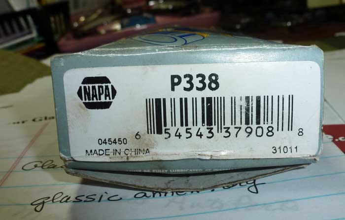
13-01    Steering column U-joint or Universal joint

In March, 2014, the owner of car 691, a 1973, found a universal joint that was a direct replacement for the one on his steering column.
This looks like the kind that go on the drive shaft, and is the knuckle that goes at the bottom of the steering column, so it can make the
bend to go into the steering box. Here are two pictures of the NAPA part, and the strange info that I found when I checked the NAPA web
page to see what cars that part fit originally. There may yet be another universal joint with the same measurements that would have come from
some Ford product of the 1970's


The cross reference says this part P338 fits 1961 to 1967 Dodge trucks and 1988 to 97 Ford trucks.

U-Joint Length (L Dimension) : 0.94" Dia. x 0.94" Dia Brg Dia. x 1.37" x 1.37" Between Grooves

It is unlikely, but not impossible that the original was a Dodge part, or this could be a totally different part with the exact measurements.


13-01-2 Sway bar end links

(1979 Phaeton) info received June, 2017

After diligently searching the internet for information on what model of Ford car was used for the Sway Bar End Links. Having no success, I stopped at a local auto repair down the road from me and ask the owner if there was any way to identify the part number for the part I needed. He said that some parts had a part number stamped on them and that should help me find a replacement part. I went home and took of the broken part from my PHAETON  but alas, no part number. I took the broken part to my local NAPA store and described my dilemma to the clerk. I gave him suggestions on what Ford Models might have

provided the part  I needed. After searching thru Granada, Fairlane, Pinto and other Models, he hit a picture of the broken end link upon looking at Mustang II. The part number that worked for me was NAPA part # 265-1922 built by Precision Engineering.

Here is a picture of that part number from the NAPA on-line website


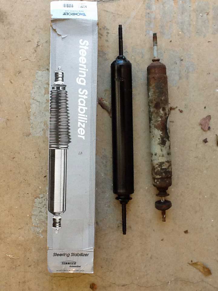
13-20    Steering Stabilizer

In 2012, Car 715 reported this source info and photo for a steering stabilizer:

from 1973 car #715
front steering stabilizer is actually from a '72 bronco

Advanced Auto Parts
Monroe steering stabilizer
part number SC2912
The stud arms on the actual new stabilizer are a little longer than the stock ones. so, all you have to do is loosen one of the mounting brackets....slide it a little....put the new stabilizer in and slide the bracket back to the original position and tighten.
 

In 2015 car 1178p (a 1974 Phaeton) sent this stabilizer info
STEERING STABILIZER -  MONROE MAGNUM SA1930

I asked Joe, the owner of car 715, for a simple explanation of the steering stabilizer:
A steering stabilizer acts just like a shock absorber. It dampens the steering feedback, dampens bumps and shimmy on the road. it helps with other steering component wear/tear.

 
You won't notice a huge difference when driving....it will just feel smoother. They last about the same amount of time as shock absorbers and should be replaced on same schedule.

 
for $30 and 30 min of time to replace....it is worth it.
 

In January of 2014, the Annexmaster took car 689 for a spin and experienced a "death wobble". This had happened only one time before, right after I got my new tires, and after a bad few minutes of the steering wheel shaking like an earthquake, it stopped and did not happen again for many months.  This time I decided to replace my stabilizer. So, I started with the above information. It seems the part (also called a steering DAMPER) part SC2912, fits a lot of different cars, and is available, altho not necessarily in stock, at many car places. Cheapest was Pep Boys, order and pay on line and pick up in a store.  It was $30 most places with 20% off at Pep Boys.  Napa was about $40.

Pep Boys did not have the item in the store, so I went with Amazon.com -- We have Amazon prime (where you pay an annual fee for "free" 2nd day postage).  I also read that the damper does not come with a boot or dust cover for the exposed shaft.(see the picture on the box below.)  Napa had them in several colors, but I ordered Black - which is part SA1997 and did not look for other colors on Amazon.  The other colors have numbers similar, such as SA1995. I saw red, blue, orange and so forth.  I will complete my story when the parts arrive. 

CAUTION -- The new stabilizer came with washers, bushings and bolts.  After pretty much chewing up the end of the stabilizer trying to tighten the nuts I figured out that I got at least one, and possibly two defective nuts.  At first I blamed the tightness on the paint on the threads, but finally took off the nut and tried it on a bolt in my parts box.  It went on a bit and locked up tight.
so TRY TO THREAD ON YOUR BOLTS ON THE WORKBENCH BEFORE INSTALLING.

Well, the parts arrived after a few days from Amazon - two different vendors - and the new part looks just like the picture.  HOWEVER, unlike the report from Car 715, my car had a minor issue that I had to fix. The new and old stabilizers look the same, but did not install the same.  I am still not quite sure why, but the OLD stabilizer was about half way extended when the car wheels were facing forward. The new one, was nearly all the way closed in. The math does not seem to work since the housing is the same size on the old and new.

The problem is, that when the rod end is connected to the wheel end, that rod goes back and forth as the wheels turn. With the new stabilizer in the same place, turning right pulled that rod toward the driver's side - well the stabilizer was almost fully closed, so it the rod could not go anywhere.  I could turn right, but barely left at all. With my mechanical skills, that could have been a solution, but it meant some serious planning of trips.

SOLUTION - I moved both end of the mounting brackets further apart about an inch or two each, so that the rod, when I was finished was about half way out, like the old one had been.  The issue, as close as I can tell, is that the new washers are the common fat ones (see the picture on the box below) and all of that takes away from the wiggle space between the two mounting posts. The old stabilizer had skinny rubbert washers, or worn out ones.  In any event, after moving the mounts apart, the car seems fine. I have only taken it around the block, and will report here only if a longer trip shows up any problems.

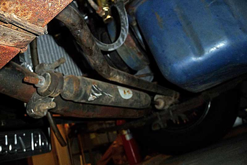
Then, in a display of mechanical ignorance, your Annexmaster went out to see why HE did not have a steering stabilizer. Oops, I do have one and here is where I found it on my car 689. My Google search of Bronco stabilizers looked like they were in FRONT of the axle where ours are behind.

Taken from under and behind the driver's side front wheel, looking toward the front of the car.
The steering stabilizer looks to be a shock absorber installed sideways between the front axle and the steering arm.

Left: looking down under the hood at the driver's side end Right: looking up from the ground at the passenger side end.
This is an older picture, but the one on the right shows how a replacement stabilizer needs to be half-way or so extended when at rest.

This is the new stabilizer in place with the dust cover. This was before I moved the mounts further apart. You can't see anything, but you can guess that not much of the rod is exposed under that cover.
When I separated the mounting brackets, I undid the dust cover on the left so I could see how much of the rod was sticking out. Before 1 inch or so, after 3 inches plus.


14-01     Suspension - rough ride fixed


In June, 2010, Mike in Yuma, AZ shared the following:

I did some work on my car 905P and I thought I'd pass it along.  As far as a rough ride, I took the middle long leaf spring out all around, then replaced the shocks with 65 mustang shocks all around.  What a difference in the ride.  No more rough riding! 


**********************


14-03     Suspension - International springs re-done

In January, 2012, Stan, the owner of car 106, had spring work done on his Southern California Phaeton.
Stan had completely re-done his car, including an engine swap and a bunch more, but found the ride rough.
After the work, I asked him what he had done, and if it made any difference. His answer:

Because of the age of the leaf springs, the car had sagged and the ride with really rough. My bump stops above the rear axle were just a half inch from the back axle causing the car to bottom out.

I had all new leafs made and fabricated for the car to ease the ride. I went from 16 individual leafs to 24. A great improvement. I am running bias ply tires* for the look with tube tires with chrome real spokes so some harsh ride is expected but really an improvement. The car is now 3 inches higher and completely level as well making the stance look great. The tires with the white walls are completely visible now which improves the look as well.

 It was a 40 mile drive home in the dark on the freeway and I cruised at 65 to 70 miles per hour all the way with the wife following in her car. It was an experience in the extreme traffic on 15 south, but we made it. I am looking into chroming the bumpers, top rests, windshield Scallions also to improve the look. I have many connection in San Diego with great prices. Tony at North County Spring in Escondido (North of San Diego, CA)  did a great job. He is really good with 35 years experience and works on Jay Leno's vehicles also. Give him a try.

Note: While it is general knowledge, I think, it is worth mentioning that RADIAL tires will significantly
improve the ride of a car compared to the old bias belted tires. I say this because both spares on my
1973 car still have bias belted tires in 2012 -- the low use of our Glassics may mean that people still have
very old non-radial tires on their cars.

****************************


15-55     Rear Ends and Gear Ratios

General info -

(or rear ends for dummies)

In 2010, after a long period of being baffled by rear end gear ratios, your Annexmaster decided to put together a primer on the subject by gathering some simple info to get you (and me) started on the subject. Questions will be asked of people who know, and the answers posted, along with any objections to the accuracy of the responses by other experts. The Mustang II group will be asked first.

The results of the Mustang II inquiry included this:

My II originally had a 2.3L (4 cyl) with a 3.55:1-- 8" rear. With the 351W, (V-8) a C4 and that
rear the car was just about impossible to move without smoking the tires.

Still pretty wild with 3.00:1 gears.

OR -- another response

Going from a 3.0 rear gear to a 4.10 makes a huge difference but you can't have
your cake and eat it too. The 4.10 will really wake up the car but at highway
speed, the motor is really screaming and your gas mileage will be crap.

Also a good explanation from Yahoo Answers:

Bottom line, the higher the ratio, the more power (Torque actually) at the rear wheels, also the higher your engine runs (RPM's) and the poorer your gas mileage.

btw - higher ratio is referred to as lower gearing (geared down) and lower ratio is referred to as higher gearing ... nice and confusing eh?

example, with a 4.10 gear set, the ratio is 4.10 to 1 so for every 4.1turns of the driveshaft, the rear axle will be turned one time and you will have a torque advantage of 4.1x
On the flip side for every say 10 turns of the wheels, your drive shaft will turn 41 times & your engine has to turn 41 times in high gear (not overdrive).
With a 3.70 gear, your Torque advantage is 3.7 times but now if your wheels turn 10 times, your drive shaft and engine will only turn 37 times. As with everything auto, always a trade off.

Changing is not difficult but is hardly a beginner project. Improperly set up and your rear end won't last long. Easy enough though to pop off the cover, slip the axles out a few inches, and then remove the differential. Once that is out, unbolt the old ring gear and bolt in the new one. The pinion isn't much harder. The trick is then shimming the differential so that the gears mesh properly and hit in the right spot. Any decent shop book should cover it well enough (Chilton's, Hayes, ect) as well as most car/truck mags from time to time (Car Craft, Petersen's 4 Wheel). A pretty easy one afternoon project.

1966-71 cars:

This info

This info relates to International based cars - the first generation of Glassics. Some of these cars ended up with V-6 and V-8 conversions, which would affect the engine speed and performance in relation to the rear end gearing.

Car 313 -- in May, 2010 Bill Crozier wrote, regarding his car with a Chevy V-8 swap. Originally he kept the rear end that came with the car (and its 4 cylinder engine).

I changed the rear end gears in mine and what a difference it made  its a real car now  the gears are still available to just change the ring and pinion changed the whole car for the better  went from 373 (factory) to 308 boy oh boy  easy fix with out mods.

Bill's son, Dennis, who owns car 189, also with a V-8 swap wrote the following, also in May, 2010:

My dad just had his (car 313) 3.73’s swapped out with 3.08’s and said it made a world of difference.  Mine is a little older with the pumpkin a little offset to the pass side.  If the numbers are good and I can get the gears, I’m gonna do the same swap.  Maybe at 60 MPH it won’t sound like it’s gonna blow up.


Chevy S-10 Rear end change after a V-8 swap

into an International car (# 189)

Reported to the Annex in 2012: I ran into some issues recently during a gear change....
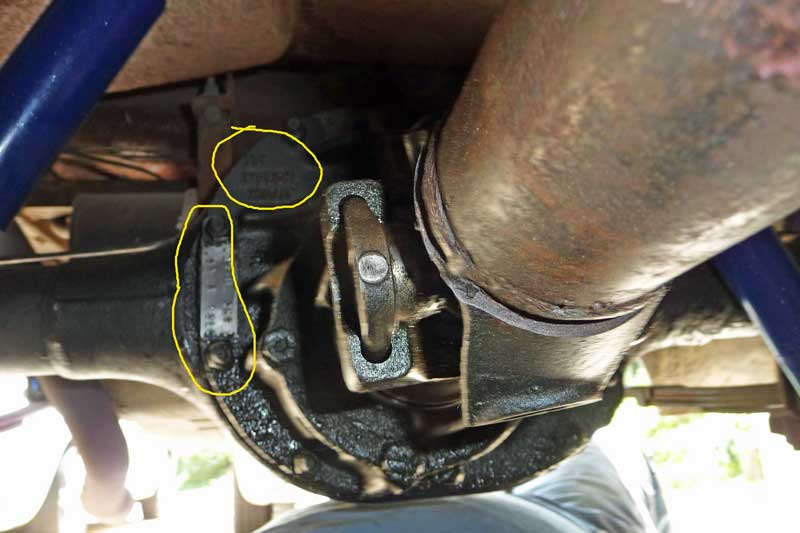
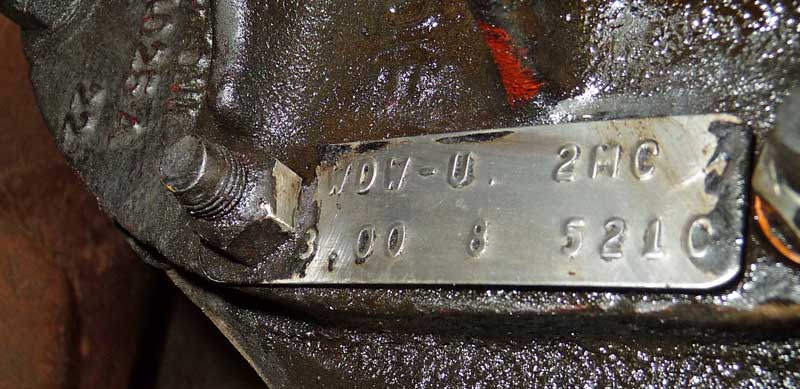
Ok, first off I did the swap for a couple of reasons: one, I wanted to be able to find parts needed; brakes, drums, wheels, etc. and the 4 lug international setup I had was very difficult to find stuff for. Second, I wanted to be able to get a lower gear so it didn't sound like it was gonna blow up running 50MPH at around 4000 RPM.

The swap was actually pretty easy. I had to cut off the spring plates from the new rear end and purchased new ones from Speedway along with the U bolts to go around the axle tubes. The new spring plates were placed directly to the inside of where the old ones were cut off and they lined up perfect to where my springs were.

 Note: make sure you have the correct angle for your rear end, up or down in relation to the rear shaft of your tranny. Lined up directly is bad. A few degrees up from center or down from center will either let you burn the tires off if you want or give you good take off and not able to spin. Of course with high HP it probably won't make a difference if you like burn outs


Anyway, I went with stock rear shocks for an 80 model Monte Carlo and fabricated mounting for the uppers on plates that were already welded to the frame. I also purchased shock plates from speedway and they also lined up perfect on the axle tubes and was able to mount the lower part of the shocks to those. I'll send pictures of all this stuff soon since the car is currently on a lift with the rear end out....again.... Good segue to the next issue.

Now, the rear end I bought was out of a 2000 S-10 with a 2.2L 5 speed. Due to the small motor and standard tranny, it had a 4:10 rear end gear in it. Therefore I didn't see a big difference with my RPM issue. No problem, I'll just put a 3:08 gear in it like my dad put in his Glassic and I'd be good to go.

Couple of things to know about GM rear ends... First, you have different size (thickness) of gears and carriers. Apparently if you have a 3:08 or lower it’s a smaller carrier. If its higher than that it's a larger carrier. Found this out the hard way after attempting to put a 3:08 in my carrier, It fit but when we tried to put it together it wouldn’t fit back in the rear end.

Second thing is apparently around 1998, GM went from a 26 spline axle to a 28 spline. Very important information when trying to match teeth on your gear to teeth on your axle. I ended up having to buy a new gear and pinion set to match the axles I had. Oh yea, I tried axles from an older S-10 and they ended up being 1/2" longer than the ones I had. I purchased a 3:23 from Summit for $173.00 and will include that part number along with the pictures.

Hope all this may help anyone looking to do this swap or anyone having trouble that has already done it. If I would have know about the gear issues prior to getting into it, it wouldn’t have been so bad. Overall it was a pretty easy swap and only took 1 day.

FOLLOWUP:  So, your Annexmaster asked Dennis what he would have done differently now that he discovered the problems that he did.  His response was:

Knowledge is power and obviously I lack a lot of it when it comes to gears and years. The Reason for an S-10 rear end was the width. It was only a fraction wider than my original. Anything (other car choices as donors for a rear end) with a V-8 was much too wide. Research would have helped with what gear came in what year and model. Still, wouldn’t bank on it unless you where the one who owned it or had first-hand knowledge of the gear in it.

If I were to do it again, Taking much more time to think it through, I would have either kept the new S-10 rear end with the 4:10 in it and put a 4 speed automatic in it or... Went with the new S-10 rear end and just planned on the lower gear and CALLED Speedway or Summit before getting into it for a good tech solution. (Mail order speed parts vendors who have very helpful customer support departments) After I called them and gave the info on what the rear end came out of they were able to give me a good solution in minutes.

The car is now on the ground and I'll be test driving it after work today.

*************************

a 1973 car:
In 2012, the Annexmaster took these photos of car 689, his 1973 Phaeton   3:00 gear ration


The rear-end markings are on the passenger side of the car. This picture is taken
from the front of the car, toward the rear. The tin tag is bolted at the top, and the
casting numbers are upside down at the top.


This picture is rotated 90 degrees so you can read the numbers.
Websites can decode the markings for you. In this case, WDW-U   2MC   3.00  8  521C

WDW-U  axle model: - in this case: "Comet- Maverick 71 - 77  8 inch, non locking, 28 spline. - the 2MC has to do with "interchange" - or sub-model?

3.00 is the gear ratio,  8 is the date, according to the chart, but it IS an 8 inch, so maybe that is what this # is
  and 521C is the plant code according to the list, but I could not match it up.
Here is where I found this:  http://www.fordification.com/tech/rearends_ford04.htm


This picture was rotated upside down so you can read the numbers.
This is the "casting number" on the front side of the rear end hub. 
C70W   4025 A    22
C7 seems to suggest 1967 - The OW do not seem to match the charts I looked at
4025 A appears to be a part number in the correct range for "rear axle".
and the 22, who knows?
 

In conclusion, it appears that the metal "dog tag" has the more useful information, especially since it includes the GEAR RATIO.

a 1974 car:

Rear end and gear ratios. -- part of the info below also appears under AOD (overdrive) transmissions.


AOD and rear end gear ratio


Received 3/2008 from Alatorre@charter.net the California owner of car 1148, a 1974 Roadster

It should be noted when changing to an AOD trans the rear gear ratio is crucial. The factors are gear ratio and tire size, as well since most AOD transmissions have a .66 to .70 overdrive.

. A 24 inch tall tire with a 3.00 gear set on the ford 8 inch at 2000 RPM is about 68 miles per hour. To really get the gear ratio right will result in the overdrive coming in at 62 MPH at 1800 to 1900 RPM. There is a formula to get the exact setup.

As to the Ford 8 inch rear the gears available are 3.00 then 3.25 , 3.55 , 3.80 , 4.11 and 4.62 there are a couple of more however not relative here. Overall tire diameter is also a big factor. There is a calculator to help you at http://www.dennysdriveshaft.com/html/potential_speed_calculator.html

 Just fill in your rear end gear the RPM you want to be at and Tire diameter hit calculate.. Then adjust the gear ratio accordingly to find what works best. PS the overdrive value I use is .70 but ask the guy who builds your trans as to the exact gear set he uses. Enter it as a decimal point value.. I hope this helps... My car is still under construction.. thanks

On my rearend (car 1174) and all Ford produced rears was a metal tab.. I decoded my tab as follows.. It is a ford 8 inch for a 74 Maverick 3.00 gear set open end (means non-posi) made in Dearborn during 3rd week of the 3rd month in 73.. I hope it helps a bit

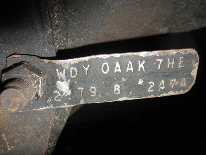
1978 cars:

The Annexmaster then checked his 1978 - car 1254 and saw the info below.

This tag was on the passenger side of the car, on the side of the hub facing the front of the car, and it was upside down - I reversed the picture.

WDY               OAAK               7HE                2.79        8                247A

http://www.woodyg.com/fairlane/finfo/fordrears.html

http://www.fordmuscle.com/forums/all-ford-techboard/470670-ford-rearend-axle-tag-codes-posted.html

The numbers on this tag seem to only somewhat relate to anything on the above websites.

The WDY code has an AA (1976-78 Mustang 3.0 gear, 8" ring gear)
and an AK (1977-78 Mustang 2.79 gear, 8" ring gear), but no OAAK -- so I guess that it should be AK, but don't know what the OA would be for.

The 7HE is a Ford internal code which I guess is not important to us..
The 2.79 on the bottom row looks like the gear ratio. THAT seems to make sense.
The 8 is where the Date is supposed to appear.
The 274A is where the plant code is supposed to be.  I found somewhere that A was for Atlanta, but no meaning to the 274 part.

Further discussion of rear ends should address the impact of using a different rear end ratio. What happens to gas mileage and acceleration if we were to change the 2.79 ratio to a 3.0, for example?

***********************

Rich, car 1148, looked up my numbers on the 1978 and came up with the following:

I have examined your tag.. I came up with as follows.. WDY is actually Maverick (Joel the builder HAS mentioned the use of Maverick parts in the past)

 OA is limited slip -- OA is for limited slip not a popular option.. Most were either open diff's or they had an L which was for traction lock..

 7HE threw me but I came up with--  7=1977 H= August E= 5th week -- Now there were 5 weeks in August 77 I had to go look it up.

247A is plant serial number ..

. I hope this helps..

This appears (to the Annexmaster) like reading tea leaves. A quick check of the web did NOT find these codes on sites listing the various Ford numbers. If my car, 1254, HAS limited slip, wow, because I can make it spin the tires by just looking at it wrong! Not all sites seem to list the same codes for the same cars. And the ones I saw did not show the date on the upper row of the tag. Rear end identification does not seem easy to do.


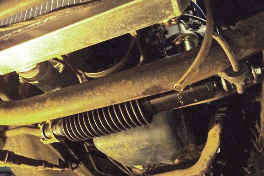
Replacing the steering rack -

Info from Mark, car 1290, (a 1978-79) received 4/2008.  See many upgrades on his car project.

Well I am in the process of replacing the steering rack. And guess what my Mustang II front end has a Pinto rack on it. Pintos used a 9/16 26 spline input shaft and Mustang used a 3/4 30 spline mine was the 9/16 unit. 

I am replacing it with a FlamingRiver 3/4 30 spline unit all Chrome and I taking off the power steering and going manual.   So if someone is replacing their steering rack they need to check the size spline and number of teeth if they want a direct replacement.

6/2008 -- When the Annexmaster asked Frank (car 1505) about how his car "tracked" at high speeds, thinking that I might want to adjust the toe-in, he replied:

I finally got my car to track down the road.  I ended up replacing the rack and pinion with a wide ratio unit out of JEG'S.  It drives 300 percent better than before. Anyone can drive it now. 


Steering Column: International

8/2008 -- An owner wrote that she had bought a replacement steering column from a Scout, and that it was fine, but way too long and had to be shortened. When I wrote to Joel, the builder, to ask about this, I got the answer below, which does not address length but another issue. I am trying to get clarification on all this, but want you to know that it is not a direct replacement as I would have thought.

You will need to shrink the outside tube of your replacement column to make it fit...   We had to cut the tube and use a piece of rubber insulation tubing as a "bearing" or spacer at the bottom to take the "wobble" out of the shaft....  maybe there is a better material available now than there was 40 years ago...  

I still had questions, so I asked the builder to explain further:

"Shrink" was probably not a good word for me to use....  Anyway, we had a tubing cutter that was large enough to cut the outside steering column tube, saving the "guts" we needed for the turn signal switch, horn wiring, and steering wheel hub.

.Then (as I remember)  we re-welded the end of the shortened tube (having taken out about 12") back to the "hub" end we needed so all that went through the fire wall was the 3/4" slip joint steering shaft...  Somewhere along the  process we used a piece of tubing insulation (like they pad roll bars in race cars) to act as a wobble bearing to keep the shaft centered or something.

Probably the best thing to tell (someone who needs to replace the steering column)  is to get a late model tilt column and do the best they can... the scout steering wheel was too big in the first place and you couldn't adapt a smaller wheel to the hub and get the turn signals and horn to work properly.... 

Pick up a mustang column and start over...  That's what I'd do.... 


1973 cars, front end. Also engine specs

From Joel, the builder, in Dec. 2008 regarding the Annexmaster's purchase of car 689, a 1973 Phaeton:

the one you have (car 689) looks like it had the round tube front axle & v-8 drive train... Should basically be a good car... the leaf springs had a tendency to "droop" and it was important to keep the front tires all filled up with air to avoid a "shimmy" when you  hit a bump or railroad just right...


Bear in mind, the early V-8's were quite power full compared to the last ones we built, so hang on when you hit it.....  Memory serves me to think about 235HP back then to 132HP in the last build (like mine)...a really big difference.... Look up a V-8 Maverick for 1971 because that was the calibration we used on the first Ford powered vehicles..... 


Steering box on an early 1977 with the leaf springs
Also  1973-74 era cars.

My 1977 #1100 has front leaf springs . what type steering box might it have ?

Joel, the builder of the cars - provided the following in 2009: Just knowing to start with FORD products is helpful, especially after recently learning that they had used trailer springs in the backs of some Glassics (around 1973-74 - maybe others)

It will have a "tag" on the top of the box that identifies the part number... That is the best info I can come up with...  Otherwise just take it to a Ford dealership and identify it as best you can visually....  the tag is the only best way I know of.... 

In October, 2010 Jim, owner of a 1973, sent the following:

I needed to replace the seal in my 1973 Glassic steering box and had to identify it so I could get the right seal. I found a website that lists the id numbers located on the tag on the steering box. The site is http://www.stangerssite.com/steeringboxtagdecoder.html

The steering box on my 1973 Glassic turned out to be a 1973 Maverick/Granada box. The pitman arm seal that should fit most manual boxes is a National 340151 or SKF 11081


Leaf spring in front end changed to coil-overs

This 1974 (car 1148) was getting an extreme makeover in 2009, and we hope to see details of this project when it is completed, but meanwhile the owner shared some pics (Pictures are in the album) and this info:

The front end is a work in progress and I will provide details soon as to how everything fits and what parts and numbers I came up with.. New fuel tank is in and brackets we made will make it easily removable from under the car. We are finishing all the bracket locations and anticipate the frame going to powder coating later this week. So far a few things have thrown us for a loop, however we are working through all the funky things that come up..

 The front suspension is a coil over adjustable ride system. Should give a significant improvement to handling and ride comfort. We are using a cross steer system for steering using a Vega style steering box. It will be manual steering however should steer easily. We are using upgraded Heim joints at all ball joint connections.

The engine is a 302 stroked to 331 cubic inches. We will be using a serpentine system which I would really never do again.. Brackets to make it work were kind of funky to line up and it extended the pulleys out about an extra 2 inches. You also have to use a reverse water pump to make it work


Rear Springs in a 1974 or similar

A question was presented to the message board in April, 2009. Since Rich, car 1148, had tried
the usual donor cars, I asked Joel, the builder, if he recalled any useful info. Below
are the question and his response.

Does anyone know what springs were used in a 1974 roadster (REAR). I need to replace the spring eye bushings and every attempt at ordering ford replacement parts has come up with the wrong ones. Any help would be greatly appreciated. I have tried Bronco, Pinto, Maverick, LTD, Mustang, Econoline, F150, I am trying to find a picture to see if international might look right..

REPLY from the original builder of the cars in 2009: Leaf springs came from Champion (i think) so the only way to fix that problem is to go to a spring shop and have his springs re-arched or purchase a replacement spring that is the same size -- the answer to the question is to go to a leaf spring house and match something up.... A trailer supply store that services boat or car trailers may be the answer....  Just start digging....   NAPA may have something is their catalog....  (you've) Just gotta start looking, but they are NOT Ford or International parts...

Later on, the builder added:

On the trailer springs in the rear.... I only suggested going to a trailer parts house to match up.... the springs we were using when the business was sold (Oct. 1972 - more info in the Glassic History Page) were manufactured by a spring house in Michigan (I think) named "Champion"....  What they did after we sold the business is the wild card.... I don't know what they did then.... I know the springs "drooped" or lost their arch pretty dependably, giving the "dropped rear end" look to the balance of the cars...   Plan on it....

Further information received in May, 2009 on this subject from Rich, car 1148

Some things I have found,,, The spring Eye is how you measure the length of the the springs, I always thought it was total overall length.. On mine the spring eye is 44.5 inches to center... I talked with Champion and ordered the closest fit bushings... I will let you know what I have to do or if they fit.

I talked to Champion they sent some spring bushings -- nylon white.. They were close but not exact.  I did make them work.. Had to go to a local hardware store and get metal sleeves to get a tight fit on the bolt.. I did get them back in and they seem to be fine. -- When I asked if we should try to pin down Champion for an exact match, he replied: The bushings, with some modification, worked however Champion did not list anything any closer so I used them.


17-01  Flywheel installed wrong originally

In August, 2011 I took car 689 (a 1973) in to a transmission shop for service. The trans had been leaking in several places
and was slipping a little.  I was not surprised when they said I needed a complete re-build.  ($1,500) Three Glassics
owned so far and 3 re-built transmissions.

That, of course, is due to the extreme age of our cars and the fact that there are tons of rubber parts in a transmission
and the fact that these cars often sit for weeks, months and years.

I was told I needed a new flywheel ($100 bucks or so) since the original one had been installed wrong and
was bent.  I was going to show a picture of a flywheel from eBay, but none of theirs seem to match mine.


NOTE - I assume that this happened at the factory, since the transmission looked un-molested,
but no way of knowing if other work had been done on the transmission over the years.

I will describe what I was told and what I saw on the one they took out.  The flywheel is a big flat metal disk
(larger than a dinner plate) with teeth all around it, I guess for the starter to engage in.  Mine
had 4 holes near the edge, and evenly spaced -- those are to mount the flywheel to the torque converter.
 

ALSO, there are two larger holes in a bit from the edge -- and THOSE are so that the drain plugs, or bolts
can poke through from the torque converter to drain fluid out of the trans. There is some kind of a bump
on the torque converter where those drains are, and, in my case the flywheel was installed
90 degrees off so the drains bumped up against the back of the flywheel rather than fitting flush into the slot holes.

I could see scratches on my old flywheel where it likely scraped or bent when the flywheel was tightened down.
What effect this had, is unclear, since the car still ran.  I have had to replace the starter TWICE in the last few hundred
miles, but its not clear if the bent flywheel had anything to do with that.

I did not see the old or new flywheels in place, but I was told that one can open the viewing panel
on the transmission, tap the starter to bring the bigger two holes into view, and see
if the drain is poking out behind the hole.  So, you do not have to take out the trans to see if this
was a one-time error or happened to your car too.

I will try to draw out the bolts and holes

x


x        O                           O          x


x

You can see that if you turn this pattern 90 degrees, the four x holes still align, but the
O holes are not in the right place.


17-02  Changed column shift
to floor shifter in a 1978

In March, 2009, John, the owner of car 1254 reported:

Last Saturday night coming home from Kissimmee, I stopped for gas and when I got back in to leave the gas station I put her into drive and had the lever come off the column.  So there I was in the middle of nowhere and a car stuck in park. 

As it turned out the entire steering column was shot and no way to fix the shifting part of the column -- main support broke off.  Well after about 2 hours of waiting for two tow trucks that never showed up I decided to see if I could get it into drive and maybe get it going just to make it home. I got under the dash and started playing with the shift cable and turning the key above me since it will not start in gear due to the neutral safety switch, and therefore felt safe.

After only about two tries she fired right up and as I started to get up  noticed the car was moving. I quickly got out and she ran over my leg.  I jumped forward and was able to land under that dash with my hand on the brake and luckily nothing got hit. Not much later I was on the way home and then to the Hospital.  Leg not broke just badly bruised. 

The steering column not repairable but was convertible to steering only with directionals (turn signals).  No problem there either.  I have attached pictures of the new Interior look, and was happy with the overall outcome.  Oh yea the neutral safety switch was broke as well, laugh on me.

The shifter I installed is a B&M Z-Gate floor shifter.  It was on the shelf at the local Auto parts store and is a cable shifter.  The only thing I did not like was that is was so low to the floor.  So I used wood as a spacer underneath and also extended the top by 3" by using double female  couplers from ACE hardware, and extending the lock linkage with a steel rod and tapping threads on one end.  

Direct swap steering column for a 1978 Roadster

Reported by Del  in Nov. 2011

Just changed my steering column on my 78 roadster. Replaced it with a 1980 Lincoln Versailles column with tilt steering. Everything fit perfect except I had to use my turn signal wiper switch. The Lincoln had an intermittent wiper switch. Mine did not. Just wired mine in and it worked perfect.

Since there were likely no 1980 steering columns available when the cars were built in 1978,
 it suggests that older Lincoln columns may also fit.  Junkyards can often tell
you which year range are interchangeable.


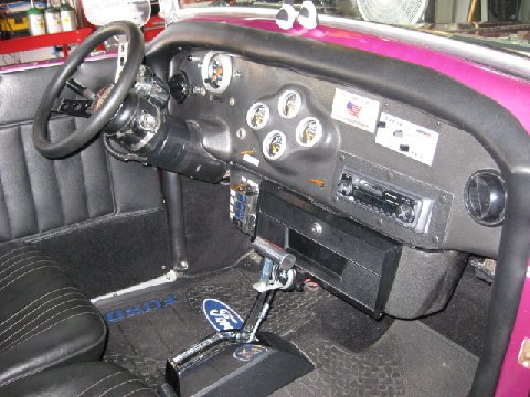
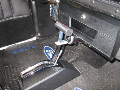
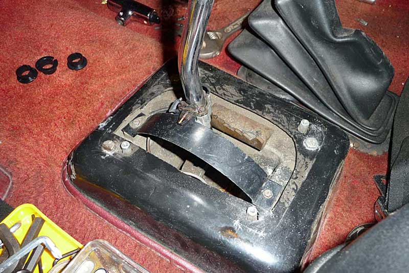
17-02 -- Floor shifter on a 1973 loose and wobbly

Start by remembering that your Annexmaster is NO KIND of mechanic, so this info may be overly simple.  When I got car 689, the floor shifter was loose and wiggly, and although it worked ok, it felt like it would lift right out of its socket on the floor.

Here is what I learned.  First, this is a common old Ford floor shifter and so answers can be found on the internet. There are a few helpful hints I learned about Glassics and these shifters.  First, there are BUSHINGS that keep the handle firm, and mine were totally GONE.  A common problem, apparently. I found this video in July, 2010 which helped put me on the right track.  http://averagejoerestoration.com/how-to/how-to-replace-mustang-automatic-shifter-bushings/

IN GLASSIC CASES, IT IS EASIEST TO NOT REMOVE THE SHIFTER BOX FROM THE CAR IF IT IS NOT LOOSE.

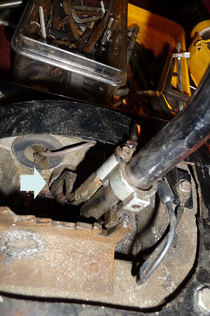
above: two bushings needed, but they shipped me 3.

First, in our Glassics, the shifter is attached differently from the Ford video.  My first mistake was to remove the chrome cover and try to loosen the 3 bolts in the fiberglass base.  That did not work like the Ford because the shifter box is bolted to the fiberglass base piece, which is then pop-riveted to the floor. When I loosened the bolt, the nut on the bottom merely fell off and disappeared.  So the three mounting bolts go down through the fiberglass housing, with a nut directly below the fiberglass piece, to hold it firmly in place, and then another nut is installed from under the car to hold the metal shifter box .

The article about the shifter bushings is temporarily interrupted at this spot to answer a question raised in 2015 - namely:

WHAT IS THAT MOUNTING STRUCTURE BETWEEN THE SHIFTER & THE TRANSMISSION HUMP?

The Mustang shifter in the original Mustangs was mounted directly on the floor of the car. In our Glassics, it is raised up on
a platform. (picture below) Where that platform came from was answered on Jan 1, 2016 by Joel, the builder of the cars.
the shifter "platform" was a unique Glassic part and if I remember correctly it was molded from a Tupper Ware (or such) food container... mother being the necessity of invention.... 

above- Tee handle taken off and cover removed- 3 bolts hold the metal shifter box - you can see the upper right, and lower left ones. The third one is behind the shift rod.  Black curved shield comes off - see the ground wire attached to the front of that curved piece.


above: another view -- I managed to break the plastic pointer on the shaft. Be careful, they dry out.

above: The arrow points to the nut that holds the stick on as well as the place where the gap was that caused the handle to wiggle. You can see how the tab that holds the shifter in each gear is almost out of the notch where it goes.

above: Here is view from the back of the car. There is a rubber plug to the right of the nut. It looks like silly putty, and
I did not need to remove it - it likely would have fallen apart anyhow.

above: the end of the shift rod once the Tee handle is off. The roller ball fits into the button
which all kind of pushes together when you put the handle back on. Pushing that roller
to the right pulls the tab out of the way so you can shift.

above: an underneath view -- You can see where I had to enlarge the hole in the floor so I could reach the nuts.
The rod that goes to the trans can be left connected and, with the nut removed inside the car, you can slide the whole thing
out just enough to slip that bushing over the shaft (after greasing it).

Since there is no room to reach that nut under the car, it is likely that the whole thing was assembled outside the car and then the base piece was installed into the car.  So I cut the opening in the bottom of the car larger so I could get a wrench (and my fingers) up in there to re-install the bolts.  If your unit is bolted firmly in place, there is no need to mess with that part at all.

In my case, I was able to install the bushings without removing the shifter box like they had done in the video. After failing at a couple of local parts places (I thought that NAPA had everything!) I ordered the bushings for $6 incl. postage from the people who did the video. (ad at the bottom of the web page with the video) I also saw them on eBay. Ordered on Wed., postmarked on Sat, and got here on Monday.  There was no communication from them after I sent the PayPal, so I was glad they actually got here.  There were 3 of them in the bag, but I think that was just a mistake.  They were thinner than I expected but worked great to tighten up the handle.  Each has a slit in it so you can lift it over the shaft without having to fully remove it from the car.

NOTE -- there are two ground wire connections that I found - remembering that our cars are fiberglass -- first, one of the bolts that holds the box in place has a ground wire attached to it under the car, held on by the nut.  When I tried to loosen the bolt from the top, that nut fell off, and the ground wire just hung there -- I think that is why the car would mostly not start -- that neutral safety switch was likely just barely grounding.  The other ground wire was attached to the black curved piece that provides the background for the shift pointer. That one was for the light inside the shifter box.

The set screw that held on the shifter T handle was totally stuck on my car, and I had to use a screw extractor to finally get it loose. It must be a common part since I found a new set screw in my junk box. 

Grease those bushings as the video suggests, and they do fit in the opening nicely, one from the inside of the box and one from the outside -- however, you may want help inside the car, as the second one wants to push the first one out of place.  My wife ended up using a box end wrench inside the car (also, the offset box wrench was how I loosened the bolt holding the handle on) -- anyhow, she used the wrench to hold the inner bushing in place while I wiggled the shaft and outer bushing till it finally slid nicely into place.